Tutorial 1: Gentium's period
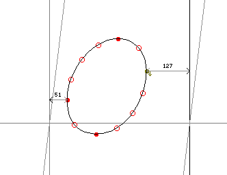
To introduce the basics of Xgridfit, let's instruct one of the simplest possible glyphs: the period. Here's what it looks like in Gentium Italic when opened in FontForge:
|
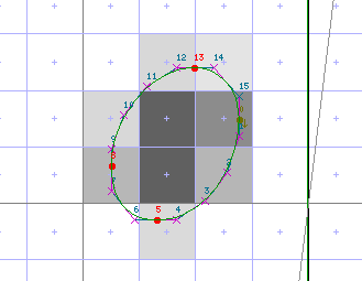
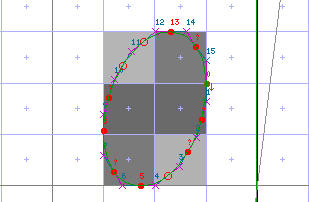
Our aim in instructing this glyph is to move key points onto the gridlines (which run between pixels) so that the TrueType rasterizer always renders the glyph cleanly, without relying too much on anti-aliasing and other tricks. Here's how the uninstructed period sits on the raster grid at twenty pixels per em; notice that none of the points falls on a gridline. The darkened squares show that the anti-aliased glyph will be a shapeless blob.
|
We need to fit only the four points at the extrema to the grid: these are numbered 0, 5, 8, and 13: a sensible start on our project would be to name these points. At the same time we will erect the elements that every Xgridfit program and every glyph program must have: <xgridfit>, <pre-program> (needed even when empty), and <glyph>:
    <?xml version="1.0"?>
    <xgridfit xmlns="http://xgridfit.sourceforge.net/Xgridfit2">

      <constant name="left-sidebearing" value="last + 1"/>

      <pre-program>
      </pre-program>

      <glyph ps-name="period">
        <constant name="last" value="15"/>
        <constant name="left" value="8"/>
        <constant name="right" value="0"/>
        <constant name="bottom" value="5"/>
        <constant name="top" value="13"/>

      </glyph>

    </xgridfit>
We have also included a global constant left-sidebearing, which gives us access to the left sidebearing point for any glyph for which we have defined the constant last (which points to the number of the last point in the glyph outline).
Let us deal first with the horizontal movements of points left and right. We'll put all the programming for horizontal movement in a with-block:
    <with-vectors axis="x">

    </with-vectors>
Our strategy will be to position point left, and then position point right relative to it. In deciding how to position left, it would help to know whether its distance from the left-sidebearing point is a standard distance in this font--that is, whether other glyphs have the same left sidebearing. In fact, the colon and the exclamation mark have the same left sidebearing of 51 font units; a control value will help us control those glyphs in a consistent way. We'll put it right after the global constant:
<control-value name="period-left-sidebearing" value="51"/>
Now we can add our first instruction to the glyph program We will position point left distance period-left-sidebearing from point left-sidebearing:
    <move distance="period-left-sidebearing">
      <reference>
        <point num="left-sidebearing"/>
      </reference>
      <point num="left"/>
    </move>
Since we have not said otherwise, it is implicit that we want the distance to be rounded so that left is positioned on a gridline.
The width of the period is also standard in this font, shared by various dots in (for example) the colon, semicolon and exclamation mark. So we need to add another control value:
<control-value name="period-width" value="232"/>
To control the width of the period we position point right relative to point left. We could do this by adding a <move> element right after the one we just wrote, like this:
    <move distance="period-width">
      <reference>
        <point num="left"/>
      </reference>
      <point num="right"/>
    </move>
But it is better to nest the new <move> element inside the other. The point in a nested <move> is always positioned relative to the point moved by the parent <move>, so we can omit the <reference> element:
    <move distance="period-left-sidebearing">
      <reference>
        <point num="left-sidebearing"/>
      </reference>
      <point num="left"/>
      <move distance="period-width">
        <point num="right"/>
      </move>
    </move>
That finishes our work on the x axis. Let's look at the result. The program so far looks like this:
<?xml version="1.0"?>
<xgridfit xmlns="http://xgridfit.sourceforge.net/Xgridfit2">

  <constant name="left-sidebearing" value="last + 1"/>

  <control-value name="period-left-sidebearing" value="51"/>
  <control-value name="period-width" value="232"/>

  <pre-program>
  </pre-program>

  <glyph ps-name="period">
    <constant name="last" value="15"/>
    <constant name="left" value="8"/>
    <constant name="right" value="0"/>
    <constant name="bottom" value="5"/>
    <constant name="top" value="13"/>

    <with-vectors axis="x">
      <move distance="period-left-sidebearing">
	<reference>
	  <point num="left-sidebearing"/>
	</reference>
	<point num="left"/>
	<move distance="period-width">
	  <point num="right"/>
	</move>
      </move>
    </with-vectors>

  </glyph>

</xgridfit>
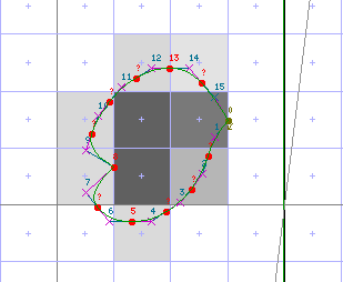
And when we run it from inside FontForge, the glyph looks like this:
|
It doesn't look like much yet, but you can see that points left and right are positioned on gridlines.
We'll start work on vertical moves by adding a with-block for the y axis:
    <with-vectors axis="y">

    </with-vectors>
The distances we have to work with here are that of point bottom from the baseline (-31) and that of point top from bottom (277). These are also standard in the font, found in the colon, exclamation mark and elsewhere. So we add control values:
    <control-value name="period-bottom" value="-31"/>
    <control-value name="period-height" value="277"/>
We'll start by positioning point bottom at position period-bottom. Since we are positioning the point on the grid rather than relative to another point, we don't need a <reference> element; and the distance will be rounded since we haven't said otherwise:
    <move distance="period-bottom">
      <point num="bottom"/>
    </move>
Then we'll position point top relative to point bottom. Once again, the preferred method is to nest a <move> element in the one we've just written:
    <move distance="period-bottom">
      <point num="bottom"/>
      <move distance="period-height">
        <point num="top"/>
      </move>
    </move>
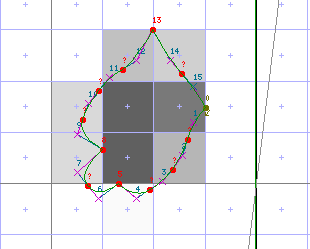
Here's the result:
|
It looks really bad because we have moved only four points of the fifteen that make up the glyph. We can position the rest automatically by adding this instruction at the end of the program:
<interpolate-untouched-points/>
And the result looks like this:
|
The glyph is rather narrow and tall at the resolution we have been using for illustration (20 pixels per em). If we want it to be rounder, we should adjust the control value period-height: that way, all of the various dots controlled by that control value will be adjusted at the same time. We add these elements to the <pre-program>:
    <round value="period-height"/>
    <control-value-delta>
      <delta-set size="11" distance="-8" cv="period-height"/>
    </control-value-delta>
The <round> element rounds the control value period-height at all resolutions. The <control-value-delta> element shrinks the distance by one pixel at 20 pixels per em (for details about the operation of delta instructions, see here). Since the distance period-height is already rounded, we can add an attribute round="no" to the element that moves top. Now when the program is run, the result looks like this:
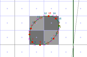
|
You can check the appearance of the period at various resolutions in FontForge or using ftview (a utility that accompanies FreeType), and add <delta-set> elements to the <control-value-delta> element as needed. Now the complete Xgridfit file is as follows:
    <?xml version="1.0"?>
    <xgridfit xmlns="http://xgridfit.sourceforge.net/Xgridfit2">

      <constant name="left-sidebearing" value="last + 1"/>

      <control-value name="period-left-sidebearing" value="51"/>
      <control-value name="period-width" value="232"/>
      <control-value name="period-bottom" value="-31"/>
      <control-value name="period-height" value="277"/>

      <pre-program>
	<round value="period-height"/>
	<control-value-delta>
	  <delta-set size="11" distance="-8" cv="period-height"/>
	</control-value-delta>
      </pre-program>

      <glyph ps-name="period">
	<constant name="last" value="15"/>
	<constant name="left" value="8"/>
	<constant name="right" value="0"/>
	<constant name="bottom" value="5"/>
	<constant name="top" value="13"/>

	<with-vectors axis="x">
	  <move distance="period-left-sidebearing">
	    <reference>
	      <point num="left-sidebearing"/>
	    </reference>
	    <point num="left"/>
	    <move distance="period-width">
	      <point num="right"/>
	    </move>
	  </move>
	</with-vectors>
	<with-vectors axis="y">
	  <move distance="period-bottom">
	    <point num="bottom"/>
	    <move distance="period-height" round="no">
	      <point num="top"/>
	    </move>
	  </move>
	</with-vectors>
	<interpolate-untouched-points/>
      </glyph>

    </xgridfit>
The illustrations above were generated by running the Xgridfit program from the FontForge GUI (File--Execute Script). If we want to run it from the command line, we must add <infile> and <outfile> elements somewhere near the top of the file:
    <infile>Gentium-Italic.sfd</infile>
    <outfile>Gentium-Italic.ttf</outfile>
And now, supposing we have named the file Gentium-Italic.xgf, we can run the program with this command:
xgridfit -f Gentium-Italic.xgf